
Page 99 - Handbook of Civil Engineering Calculations, Second Edition
P. 99
1.82 STRUCTURAL STEEL ENGINEERING AND DESIGN
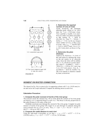
2. Determine the required
number of rows of rivets
Adopt, tentatively, the minimum
allowable pitch, which is 2 in. (50.8
mm) for /4-in. (19.05-mm) rivets.
3
Then establish a feasible rivet pitch.
From an earlier calculation procedure
in this section, R ss 6630 lb
(29,490.0 N). Then T 7425(2)
6630n; n 2.24. Use the next largest
whole number of rows, or three rows
of rivets. Also, L max 3(6630)/7425
1
2.68 in. (68.072 mm). Use a 2 /2-
in. (63.5-mm) pitch, as shown in Fig.
57a.
3. Determine the plate
thickness
Establish the thickness t in (mm) of
the steel plates by equating the stress
on the net section to its allowable
value. Since the holes will be drilled,
13
take /16 in. (20.64 mm) as their diam-
eter. Then T 22,000t(2.5 0.81)
7425(2.5); t 0.50 in. (12.7 mm); use
1 /2-in. (12.7-mm) plates. Also, R b
36,380(0.5) > 6630 lb (29,490.2 N).
The rivet capacity is therefore limited
by shear, as assumed.
FIGURE 57
MOMENT ON RIVETED CONNECTION
The channel in Fig. 58a is connected to its supporting column with /4-in. (19.05-mm) riv-
3
ets and resists the couple indicated. Compute the shearing stress in each rivet.
Calculation Procedure:
1. Compute the polar moment of inertia of the rivet group
The moment causes the channel (Fig. 58) to rotate about the centroid of the rivet group
and thereby exert a tangential thrust on each rivet. This thrust is directly proportional to
the radial distance to the center of the rivet.
Establish coordinate axes through the centroid of the rivet group. Compute the polar
moment of inertia of the group with respect to an axis through its centroid, taking the
2
2
2
2
cross-sectional area of a rivet as unity. Thus, J (x y ) 8(2.5) 4(1.5)
2
2
4(4.5) 140 sq.in. (903.3 cm ).
2. Compute the radial distance to each rivet
2 0.5
2
Using the right-angle relationship, we see that r 1 r 4 (2.5 4.5 ) 5.15 in.
2
2 0.5
(130.810 mm); r 2 r 3 (2.5 1.5 ) 2.92 in. (74.168 mm).