
Page 102 - Handbook of Civil Engineering Calculations, Second Edition
P. 102
STATICS, STRESS AND STRAIN, AND FLEXURAL ANALYSIS 1.85
8. Compute the force on the rivets
Considering rivets 1 and 2, use the equation F Mr
/J, where r
distance from the in-
stantaneous center of rotation O to the center of the given rivet, in. For rivets 1 and 2, r
7.45 in. (189.230 mm). Then F 90,000(7.45)/118 5680 lb (25,264.6 N). The force on
rivet 1 has an action line normal to the radius OA.
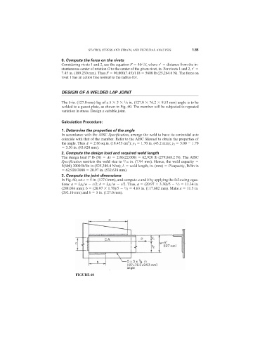
DESIGN OF A WELDED LAP JOINT
3
The 5-in. (127.0-mm) leg of a 5 3 /8 in. (127.0 76.2 9.53 mm) angle is to be
welded to a gusset plate, as shown in Fig. 60. The member will be subjected to repeated
variation in stress. Design a suitable joint.
Calculation Procedure:
1. Determine the properties of the angle
In accordance with the AISC Specification, arrange the weld to have its centroidal axis
coincide with that of the member. Refer to the AISC Manual to obtain the properties of
2
the angle. Thus A 2.86 sq.in. (18.453 cm ); y 1 1.70 in. (43.2 mm); y 2 5.00 1.70
3.30 in. (83.820 mm).
2. Compute the design load and required weld length
The design load P lb (N) As 2.86(22,000) 62,920 lb (279,868.2 N). The AISC
Specification restricts the weld size to /16 in. (7.94 mm). Hence, the weld capacity
5
5(600) 3000 lb/lin in (525,380.4 N/m); L weld length, in. (mm) P/capacity, lb/lin in
62,920/3000 20.97 in. (532.638 mm).
3. Compute the joint dimensions
In Fig. 60, set c 5 in. (127.0 mm), and compute a and b by applying the following equa-
tions: a Ly 2 /w c/2; b Ly 1 /w c/2. Thus, a (20.97 3.30)/5 /2 11.34 in.
5
5
(288.036 mm); b (20.97 1.70)/5 /2 4.63 in. (117.602 mm). Make a 11.5 in.
(292.10 mm) and b 5 in. (127.0 mm).
FIGURE 60