
Page 101 - Handbook of Civil Engineering Calculations, Second Edition
P. 101
1.84 STRUCTURAL STEEL ENGINEERING AND DESIGN
FIGURE 59
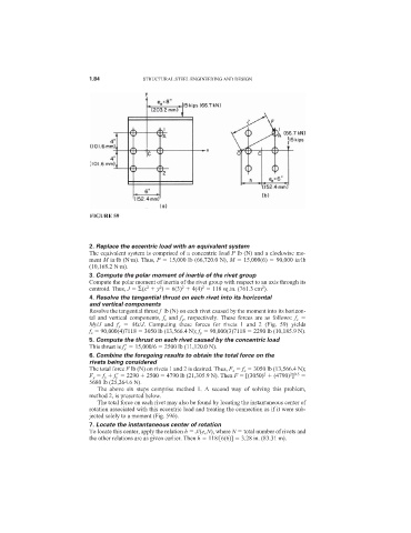
2. Replace the eccentric load with an equivalent system
The equivalent system is comprised of a concentric load P lb (N) and a clockwise mo-
ment M in·lb (N·m). Thus, P 15,000 lb (66,720.0 N), M 15,000(6) 90,000 in·lb
(10,168.2 N·m).
3. Compute the polar moment of inertia of the rivet group
Compute the polar moment of inertia of the rivet group with respect to an axis through its
2
2
2
2
2
centroid. Thus, J (x y ) 6(3) 4(4) 118 sq.in. (761.3 cm ).
4. Resolve the tangential thrust on each rivet into its horizontal
and vertical components
Resolve the tangential thrust f lb (N) on each rivet caused by the moment into its horizon-
tal and vertical components, f x and f y , respectively. These forces are as follows: f x
My/J and f y Mx/J. Computing these forces for rivets 1 and 2 (Fig. 59) yields
f x 90,000(4)7118 3050 lb (13,566.4 N); f y 90,000(3)7118 2290 lb (10,185.9 N).
5. Compute the thrust on each rivet caused by the concentric load
This thrust is f y
15,000/6 2500 lb (11,120.0 N).
6. Combine the foregoing results to obtain the total force on the
rivets being considered
The total force F lb (N) on rivets 1 and 2 is desired. Thus, F x f x 3050 lb (13,566.4 N);
2
2 0.5
F y f y f y
2290 2500 4790 lb (21,305.9 N). Then F [(3050) (4790) ]
5680 lb (25,264.6 N).
The above six steps comprise method 1. A second way of solving this problem,
method 2, is presented below.
The total force on each rivet may also be found by locating the instantaneous center of
rotation associated with this eccentric load and treating the connection as if it were sub-
jected solely to a moment (Fig. 59b).
7. Locate the instantaneous center of rotation
To locate this center, apply the relation h J/(e e N), where N total number of rivets and
the other relations are as given earlier. Then h 118/[6(6)] 3.28 in. (83.31 m).