
Page 100 - Handbook of Civil Engineering Calculations, Second Edition
P. 100
STATICS, STRESS AND STRAIN, AND FLEXURAL ANALYSIS 1.83
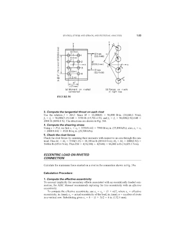
FIGURE 58
3. Compute the tangential thrust on each rivet
Use the relation f Mr/J. Since M 12,000(8) 96,000 lb·in. (10,846.1 N·m),
f 1 f 4 96,000(5.15)/140 3530 lb (15,701.4 N); and f 2 f 3 96,000(2.92)/140
2000 lb (8896.0 N). The directions are shown in Fig. 58b.
4. Compute the shearing stress
Using s P/A, we find s 1 s 4 3530/0.442 7990 lb/sq.in. (55,090 kPa); also, s 2 s 3
2000/0.442 4520 lb/sq.in. (29,300 kPa).
5. Check the rivet forces
Check the rivet forces by summing their moments with respect to an axis through the cen-
troid. Thus M 1 M 4 3530(5.15) 18,180 in·lb (2054.0 N·m); M 2 M 3 2000(2.92)
5840in·lb (659.8 N·m). Then EM 4(18,180) 4(5840) 96,080 in·lb (10,855.1 N·m).
ECCENTRIC LOAD ON RIVETED
CONNECTION
Calculate the maximum force exerted on a rivet in the connection shown in Fig. 59a.
Calculation Procedure:
1. Compute the effective eccentricity
To account implicitly for secondary effects associated with an eccentrically loaded con-
nection, the AISC Manual recommends replacing the true eccentricity with an effective
eccentricity.
To compute the effective eccentricity, use e e e a (1 n)/2, where e e effective
eccentricity, in. (mm); e a actual eccentricity of the load, in. (mm); n number of rivets
in a vertical row. Substituting gives e e 8 (1 3)/2 6 in. (152.4 mm).