
Page 98 - Handbook of Civil Engineering Calculations, Second Edition
P. 98
STATICS, STRESS AND STRAIN, AND FLEXURAL ANALYSIS 1.81
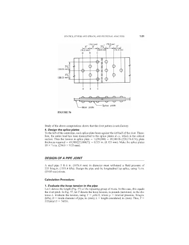
FIGURE 56
Study of the above computations shows that the rivet pattern is satisfactory.
4. Design the splice plates
To the left of the centerline, each splice plate bears against the left half of the rivet. There-
fore, the entire load has been transmitted to the splice plates at cc, which is the critical
section. Thus the tension in splice plate /2(99,000) 49,500 lb (220,176.0 N); plate
1
thickness required 49,500/[22,000(7)] 0.321 in. (8.153 mm). Make the splice plates
10 /8 in. (254.0 9.53 mm).
3
DESIGN OF A PIPE JOINT
A steel pipe 5 ft 6 in. (1676.4 mm) in diameter must withstand a fluid pressure of
225 lb/sq.in. (1551.4 kPa). Design the pipe and the longitudinal lap splice, using /4-in.
3
(19.05-mm) rivets.
Calculation Procedure:
1. Evaluate the hoop tension in the pipe
Let L denote the length (Fig. 57) of the repeating group of rivets. In this case, this equals
the rivet pitch. In Fig. 57, let T denote the hoop tension, in pounds (newtons), in the dis-
tance L. Evaluate the tension, using T pDL/2, where p internal pressure, lb/sq.in.
(kPa); D inside diameter of pipe, in. (mm); L length considered, in. (mm). Thus, T
225(66)L/2 7425L.