
Page 90 - Handbook of Civil Engineering Calculations, Second Edition
P. 90
STATICS, STRESS AND STRAIN, AND FLEXURAL ANALYSIS 1.73
5. Place the system in the position thus established,
and compute V de
Thus, R L 50(100 6 13.8)/200 23.1 kips (102.75 kN). The load at panel point d is
P d 5(6)/25 1.2 kips (5.34 kN); V de 23.1 1.2 21.9 kips (97.41 kN).
6. Assume left-to-right locomotion; proceed as in step 3
Consider that load 4 is within panel de and the remaining loads are to the right of this pan-
el. Proceeding as in step 3, we find dV de /dx 15(7/200) 35( 1/200) > 0.
So, as the system moves from left to right, V de is maximum at the instant that load 4 is at e.
7. Place the system in the position thus established, and
compute V de
Thus V de R L [50(100 8.2)1/200 23.0 kips (102.30 kN); V de, max 23.0 kips
(102.30 kN).
8. Compute the maximum tensile force in De
Using the same relation as in step 3 of the previous calculation procedure, we find csc
2 0.5
2
2
[(25 30 )/30 ] 1.30; then De 23.0(1.30) 29.9-kip (133.00-kN) tension.
INFLUENCE LINE FOR BENDING MOMENT
IN BRIDGE TRUSS
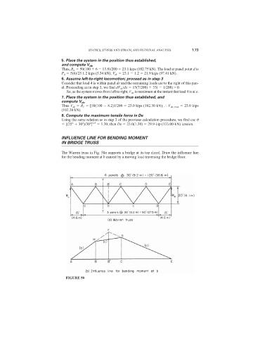
The Warren truss in Fig. 50a supports a bridge at its top chord. Draw the influence line
for the bending moment at b caused by a moving load traversing the bridge floor.
FIGURE 50