
Page 119 - Handbook of Electrical Engineering
P. 119
INDUCTION MOTORS 101
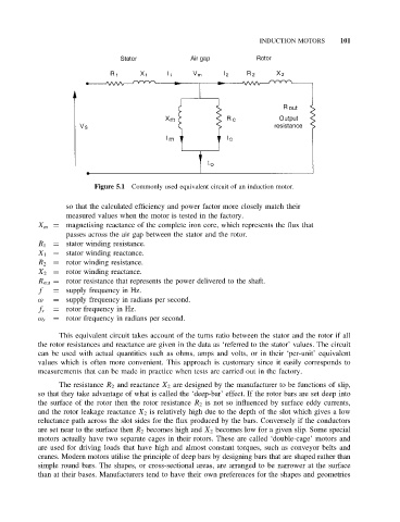
Figure 5.1 Commonly used equivalent circuit of an induction motor.
so that the calculated efficiency and power factor more closely match their
measured values when the motor is tested in the factory.
X m = magnetising reactance of the complete iron core, which represents the flux that
passes across the air gap between the stator and the rotor.
R 1 = stator winding resistance.
X 1 = stator winding reactance.
R 2 = rotor winding resistance.
X 2 = rotor winding reactance.
R out = rotor resistance that represents the power delivered to the shaft.
f = supply frequency in Hz.
ω = supply frequency in radians per second.
f r = rotor frequency in Hz.
= rotor frequency in radians per second.
ω r
This equivalent circuit takes account of the turns ratio between the stator and the rotor if all
the rotor resistances and reactance are given in the data as ‘referred to the stator’ values. The circuit
can be used with actual quantities such as ohms, amps and volts, or in their ‘per-unit’ equivalent
values which is often more convenient. This approach is customary since it easily corresponds to
measurements that can be made in practice when tests are carried out in the factory.
The resistance R 2 and reactance X 2 are designed by the manufacturer to be functions of slip,
so that they take advantage of what is called the ‘deep-bar’ effect. If the rotor bars are set deep into
the surface of the rotor then the rotor resistance R 2 is not so influenced by surface eddy currents,
and the rotor leakage reactance X 2 is relatively high due to the depth of the slot which gives a low
reluctance path across the slot sides for the flux produced by the bars. Conversely if the conductors
are set near to the surface then R 2 becomes high and X 2 becomes low for a given slip. Some special
motors actually have two separate cages in their rotors. These are called ‘double-cage’ motors and
are used for driving loads that have high and almost constant torques, such as conveyor belts and
cranes. Modern motors utilise the principle of deep bars by designing bars that are shaped rather than
simple round bars. The shapes, or cross-sectional areas, are arranged to be narrower at the surface
than at their bases. Manufacturers tend to have their own preferences for the shapes and geometries