
Page 140 - Handbook of Electrical Engineering
P. 140
122 HANDBOOK OF ELECTRICAL ENGINEERING
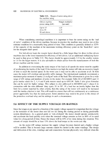
Table 5.11. Margin of motor rating above
the machine rating
Driven machine Margin multiplier
power rating (kW) (per-unit)
Up to 15 1.25
16 to 55 1.15
56 and above 1.10
When considering centrifugal machines it is important to base the motor rating on the ‘end
of curve’ condition of the driven machine, because in practice the machine may need to run at this
extreme condition for a reasonably long period of time. This condition is generally defined as 125%
of the capacity of the machine at the maximum working efficiency point on the ‘head-flow’ curve
for the designed shaft speed.
For belt-driven loads the margin factor should be a little larger than for direct in-line driven
machines due to the lower transmission efficiency of belt drives. Let an additional multiplying factor
be used to that given in Table 5.11. This factor should be approximately 1.2 for the smaller motors
to 1.4 for the larger motors. It is also advisable to obtain advice from the manufacturers of both the
driven machine and the motor.
In addition to overcoming the static torque of the load at all speeds the motor must be capable
of accelerating the inertia of the load. If the inertia is too high the motor will take an excessive length
of time to reach the desired speed. In the worst case it may not be able to accelerate at all. In both
cases the motor will overheat and possibly suffer damage. The international standards recommend a
2
maximum polar moment of inertia (J)inkg m units of the load. This information is given for a wide
range of kW ratings and numbers of poles in the motor. For example Table III of IEC60034 part 12
gives inertia values for 2, 4, 6 and 8 pole motors rated up to 630 kW. Table 5 also gives formulae
that can be used for higher ratings. This subject is also addressed in IEC60034 part 1 clause 6 in
connection with the nine different ‘duty types, S1 to S9’. If a load has an inertia higher than the
limit for a motor matched by other criteria, then the rating of the motor will need to be increased
until the inertia criterion is met. This will result in a motor that will run continuously at a continuous
power appreciably less than its rated power. Some attention may need to be given to the choice of
the protective overload relay and its settings in such a circumstance.
5.6 EFFECT OF THE SUPPLY VOLTAGE ON RATINGS
Since the torque at any speed is a function of the supply voltage squared it is important that the voltage
at the terminals of the motor does not fall too far during the starting period or during predictable
system disturbances. As a general guide or ‘rule-of-thumb’ the motor should operate satisfactorily
and accelerate the load quickly even when the terminal voltage remains as low as 80% of its rated
value for a long period of time. Hence the torque will be 64% of its value during this situation. This
amount of torque should be at least 15% above the load torque at the worst-case slip.
As the motor kW ratings increase the supply voltage becomes limited and a higher voltage
will be needed. This is because large currents cannot be carried in the stator windings. The design
and fabrication of the slots, windings and end connections become physically very difficult when the