
Page 138 - Handbook of Electrical Engineering
P. 138
120 HANDBOOK OF ELECTRICAL ENGINEERING
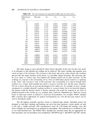
Table 5.10. Per-unit reactances for equivalent double-cage two-pole motors
Rated power Slip (pu) X 20 X 21 X 22 X 33
(kW)
LV — — — — —
11 0.0433 0.114 0.0531 0.05442 1.1944
15 0.0355 0.124 0.0528 0.05573 0.4755
22 0.0282 0.137 0.0527 0.05619 0.3236
30 0.0237 0.147 0.0529 0.05571 0.2899
37 0.0216 0.153 0.0532 0.05596 0.2741
45 0.0191 0.159 0.0536 0.05640 0.2678
55 0.0173 0.165 0.0541 0.05716 0.2635
75 0.0150 0.173 0.0551 0.05882 0.2591
90 0.0138 0.178 0.0558 0.06012 0.2591
110 0.0126 0.182 0.0567 0.06195 0.2590
132 0.0117 0.186 0.0576 0.06357 0.2590
160 0.0108 0.189 0.0587 0.06601 0.2582
200 0.00995 0.193 0.0601 0.06892 0.2594
250 0.00917 0.196 0.0617 0.07223 0.2593
315 0.00846 0.198 0.0635 0.07597 0.2586
HV — — — — —
630 0.00887 0.0961 0.0471 0.07070 0.1413
800 0.00896 0.0935 0.0470 0.06432 0.1493
1100 0.00901 0.0912 0.0477 0.06695 0.1433
2500 0.00883 0.0917 0.0537 0.08472 0.1173
5000 0.00842 0.0991 0.0651 0.08768 0.1101
The stator design is more affected by these factors than that of the rotor but the rotor needs
to be designed so that efficient fan cooling can be achieved. The stator winding and magnetic iron
circuit are part of the enclosure. The enclosure is the frame and casing which anchors the windings
and provides the fixing structure of the motor, e.g. bed-plate, flange mounting. The enclosure may
be of an ‘open’ or ‘closed’ type. The simplest and cheapest motors use an open enclosure. All the
windings are exposed to the surrounding air by virtue of deliberately placed windows or openings
at the ‘drive’ and ‘non-drive’ ends of the enclosure. The surrounding air is drawn through these
windows by a simple shaft-mounted fan which is used to cool the rotor and the stator materials.
The air is drawn along the air gap and discharged at the outlet end. An example of such a simple
construction is a modern domestic washing machine or vacuum cleaner, but in an industrial situation
this design would be deemed unsafe to human operators and would be exposed to any kind of
pollution present in the cooling air, e.g. moisture, dust, chemicals, flammable gas. There are several
forms of open-type motors as defined in American documentation. For example NEMA standard
MG1 classifies those appropriate for general non-hazardous use. Not all open-type motors can be
used in oil industry plants.
The oil industry normally specifies closed or enclosed type motors. Industrial motors are
designed so that their windings and bearings are given the least exposure to poor quality air and,
to this end, a ‘totally enclosed’ (TE) construction is used. In a TE design the bearings, rotor and
stator windings are surrounded by an enclosed air atmosphere. The enclosed air is circulated by one
or two shaft-mounted fans. The NEMA MG1 standard also classifies those that are appropriate for
both hazardous and non-hazardous area installations. IEC60034 part 5, IEC60079 and NEC articles