
Page 146 - Handbook of Electrical Engineering
P. 146
128 HANDBOOK OF ELECTRICAL ENGINEERING
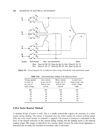
Figure 5.8 Circuit diagram for an induction motor using a Korndorfer auto-transformer starter.
Table 5.14. Auto-transformer starting of an induction motor
Voltage applied Line current Motor current Locked rotor
to motor in in per cent of in per cent of torque in per cent
per cent of locked rotor locked rotor of full voltage
rated voltage current current value
100 100 100 100
90 81 90 81
80 64 80 64
70 49 70 49
60 36 60 36
50 25 50 25
5.10.4 Series Reactor Method
A standard design of motor is used. This is a simple method that requires the insertion of a series
reactor during starting. The reactor is bypassed once the motor reaches its normal working speed.
Only one extra circuit breaker or contactor is required. The amount of reactance is calculated on the
basis of the desired reduction of line current during starting, but the limiting factor is the reduced
starting torque. The torque is reduced for two reasons, firstly because the total circuit impedance is
increased and secondly the reactance-to-resistance ratio is increased.