
Page 150 - Handbook of Electrical Engineering
P. 150
TRANSFORMERS 133
what is called the ‘referred’ components. For example if the secondary winding impedance R s + jX s
is referred to as the primary side then the referred or equivalent impedance R + jX in the primary
s
s
circuit is,
R s + jX s
R + jX =
s s 2
N
Hence the total series impedance in the primary circuit becomes,
Z p = (R p + R ) + j(X p + X ) ohms.
s s
At this stage all the components are ohmic values and are obtainable from tests.
The per-unit impedance Z pu can be simply derived from the ohmic impedance values and
knowing either the primary rated current or the kVA rating of the transformer. It will, however, be
seen that the per-unit impedance Z pu is the same whether it is calculated from the primary or the
secondary data.
The standard kVA ratings of transformers follow the numbering sequence of ISO3 or BS2045
for units designed on the basis of European practice, e.g. 100, 125, 160, 200, 250, 315, 400, 500,
630, 800 kVA and decades above and below.
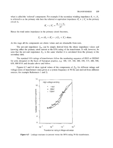
Figures 6.3 and 6.4 show typical values of the components of Z pu for different ratings and
voltage ratios of transformers (data given at a system frequency of 50 Hz and derived from different
sources, for example References 1 and 2).
Figure 6.3 Leakage reactance in percent versus the MVA rating 50 Hz transformers.