
Page 154 - Handbook of Electrical Engineering
P. 154
TRANSFORMERS 137
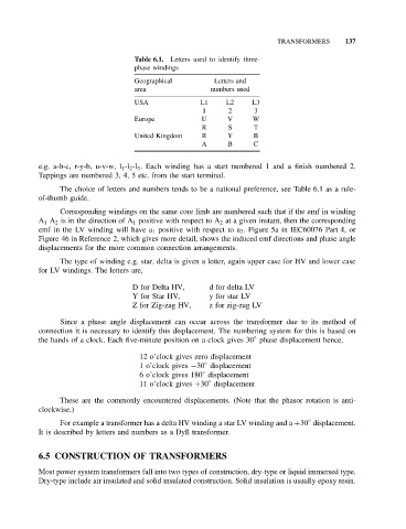
Table 6.1. Letters used to identify three-
phase windings
Geographical Letters and
area numbers used
USA L1 L2 L3
1 2 3
Europe U V W
R S T
United Kingdom R Y B
A B C
e.g. a-b-c, r-y-b, u-v-w, l 1 -l 2 -l 3 . Each winding has a start numbered 1 and a finish numbered 2.
Tappings are numbered 3, 4, 5 etc. from the start terminal.
The choice of letters and numbers tends to be a national preference, see Table 6.1 as a rule-
of-thumb guide.
Corresponding windings on the same core limb are numbered such that if the emf in winding
A 1 A 2 is in the direction of A 1 positive with respect to A 2 at a given instant, then the corresponding
emf in the LV winding will have a 1 positive with respect to a 2 . Figure 5a in IEC60076 Part 4, or
Figure 46 in Reference 2, which gives more detail, shows the induced emf directions and phase angle
displacements for the more common connection arrangements.
The type of winding e.g. star, delta is given a letter, again upper case for HV and lower case
for LV windings. The letters are,
D for Delta HV, d for delta LV
Y for Star HV, y for star LV
Z for Zig-zag HV, z for zig-zag LV
Since a phase angle displacement can occur across the transformer due to its method of
connection it is necessary to identify this displacement. The numbering system for this is based on
◦
the hands of a clock. Each five-minute position on a clock gives 30 phase displacement hence,
12 o’clock gives zero displacement
◦
1 o’clock gives −30 displacement
◦
6 o’clock gives 180 displacement
◦
11 o’clock gives +30 displacement
These are the commonly encountered displacements. (Note that the phasor rotation is anti-
clockwise.)
◦
For example a transformer has a delta HV winding a star LV winding and a +30 displacement.
It is described by letters and numbers as a Dyll transformer.
6.5 CONSTRUCTION OF TRANSFORMERS
Most power system transformers fall into two types of construction, dry-type or liquid immersed type.
Dry-type include air insulated and solid insulated construction. Solid insulation is usually epoxy resin.