
Page 354 - Handbook of Electrical Engineering
P. 354
PROTECTIVE RELAY COORDINATION 341
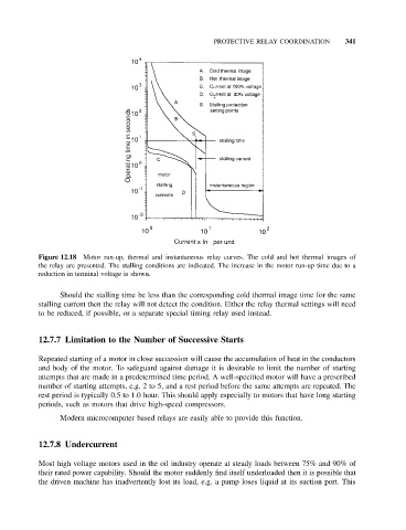
Figure 12.18 Motor run-up, thermal and instantaneous relay curves. The cold and hot thermal images of
the relay are presented. The stalling conditions are indicated. The increase in the motor run-up time due to a
reduction in terminal voltage is shown.
Should the stalling time be less than the corresponding cold thermal image time for the same
stalling current then the relay will not detect the condition. Either the relay thermal settings will need
to be reduced, if possible, or a separate special timing relay used instead.
12.7.7 Limitation to the Number of Successive Starts
Repeated starting of a motor in close succession will cause the accumulation of heat in the conductors
and body of the motor. To safeguard against damage it is desirable to limit the number of starting
attempts that are made in a predetermined time period. A well-specified motor will have a prescribed
number of starting attempts, e.g. 2 to 5, and a rest period before the same attempts are repeated. The
rest period is typically 0.5 to 1.0 hour. This should apply especially to motors that have long starting
periods, such as motors that drive high-speed compressors.
Modern microcomputer based relays are easily able to provide this function.
12.7.8 Undercurrent
Most high voltage motors used in the oil industry operate at steady loads between 75% and 90% of
their rated power capability. Should the motor suddenly find itself underloaded then it is possible that
the driven machine has inadvertently lost its load, e.g. a pump loses liquid at its suction port. This