
Page 356 - Handbook of Electrical Engineering
P. 356
PROTECTIVE RELAY COORDINATION 343
Note: For small motors, e.g. 22 kW and below, the earth loop impedance including the feeder cable
armouring may be too high. When this is the situation a risk of electric shock exists during
a short circuit at or near to the motor. To reduce the exposure to the risk it is necessary to
use a 51 N or a 50 N core balance current transformer and relay at the motor control centre.
The choice of a 50 N is preferred subject to the contactor being properly coordinated with its
upstream fuses.
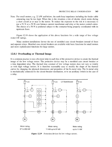
Figure 12.19 shows the application of the above functions for a wide range of low voltage
motor kW ratings.
Many modern installations favour the use of moulded case circuit breakers instead of fuses
and separate relays. Moulded case circuit breakers are available with basic functions for small motors
and more sophisticated functions for large motors.
12.8.1 Overloading or Thermal Image
It is common practice to use a bi-metal strip in each line of the protective device to create the thermal
image of the low voltage motor. The protective device may be a moulded case circuit breaker or
a time dependent relay. The thermal time constant of low voltage motors does not vary so widely
as with high voltage motors. It is therefore reasonably easy to modify the shape of the thermal
curves by changing the physical dimensions and properties of the bi-metal strip. The bi-metal strip
is mechanically connected to the circuit breaker mechanism, or to an auxiliary switch in the case of
arelay.
Figure 12.19 Protection devices for low voltage motors.