
Page 360 - Handbook of Electrical Engineering
P. 360
PROTECTIVE RELAY COORDINATION 347
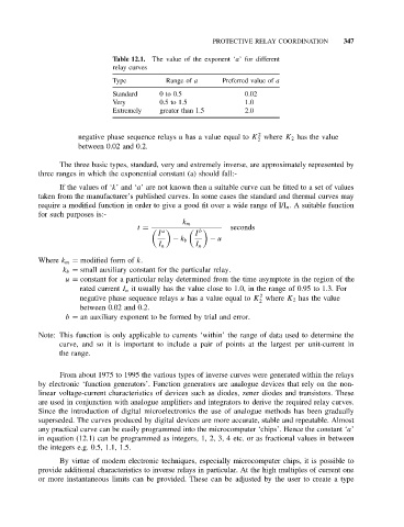
Table 12.1. The value of the exponent ‘a’ for different
relay curves
Type Range of a Preferred value of a
Standard 0 to 0.5 0.02
Very 0.5to1.5 1.0
Extremely greater than 1.5 2.0
2
negative phase sequence relays u has a value equal to K where K 2 has the value
2
between 0.02 and 0.2.
The three basic types, standard, very and extremely inverse, are approximately represented by
three ranges in which the exponential constant (a) should fall:-
If the values of ‘k’and ‘a’ are not known then a suitable curve can be fitted to a set of values
taken from the manufacturer’s published curves. In some cases the standard and thermal curves may
require a modified function in order to give a good fit over a wide range of I/I n . A suitable function
for such purposes is:-
k m
seconds
I I
t = a b
− k b − u
I n I n
Where k m = modified form of k.
k b = small auxiliary constant for the particular relay.
u = constant for a particular relay determined from the time asymptote in the region of the
rated current I n it usually has the value close to 1.0, in the range of 0.95 to 1.3. For
2
negative phase sequence relays u has a value equal to K where K 2 has the value
2
between 0.02 and 0.2.
b = an auxiliary exponent to be formed by trial and error.
Note: This function is only applicable to currents ‘within’ the range of data used to determine the
curve, and so it is important to include a pair of points at the largest per unit-current in
the range.
From about 1975 to 1995 the various types of inverse curves were generated within the relays
by electronic ‘function generators’. Function generators are analogue devices that rely on the non-
linear voltage-current characteristics of devices such as diodes, zener diodes and transistors. These
are used in conjunction with analogue amplifiers and integrators to derive the required relay curves.
Since the introduction of digital microelectronics the use of analogue methods has been gradually
superseded. The curves produced by digital devices are more accurate, stable and repeatable. Almost
any practical curve can be easily programmed into the microcomputer ‘chips’. Hence the constant ‘a’
in equation (12.1) can be programmed as integers, 1, 2, 3, 4 etc. or as fractional values in between
the integers e.g. 0.5, 1.1, 1.5.
By virtue of modern electronic techniques, especially microcomputer chips, it is possible to
provide additional characteristics to inverse relays in particular. At the high multiples of current one
or more instantaneous limits can be provided. These can be adjusted by the user to create a type