
Page 361 - Handbook of Electrical Engineering
P. 361
348 HANDBOOK OF ELECTRICAL ENGINEERING
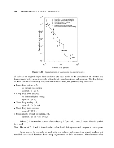
Figure 12.21 Operating time of a composite inverse time relay.
of staircase or stepped shape. Such additions are very useful in the coordination of incomer and
interconnector relays at switchboards, with other devices downstream and upstream. The descriptions
of these features occasionally vary between manufacturers, but generally they are called:
• Long delay setting, ×I n
or current plug setting
symbol I> (or I 1 )
• Long delay time, seconds
or time multiplier setting
symbol T(I >)
• Short delay setting, ×I n
symbol I (or I 2 )
• Short delay time, seconds
symbol T(I )
• Instantaneous or high-set setting, ×I n
symbol I or I ≫ or (I 3 )
Where I n is the nominal current of the relay e.g. 1.0 per unit, 1 amp, 5 amps. Also the symbol
I o is used.
Note: The use of I o , I 1 and I 2 should not be confused with their symmetrical component counterparts.
Some relays, for example as used with low voltage high current air circuit breakers and
moulded case circuit breakers, have many adjustments to their parameters. Manufacturers often