Page 451 - Handbook of Electrical Engineering
P. 451

440    HANDBOOK OF ELECTRICAL ENGINEERING

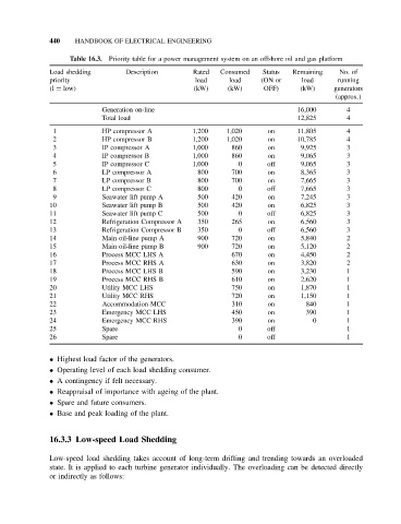
                    Table 16.3. Priority table for a power management system on an offshore oil and gas platform

              Load shedding        Description       Rated  Consumed   Status  Remaining    No. of
              priority                               load     load     (ON or     load     running
              (l = low)                              (kW)     (kW)     OFF)      (kW)     generators
                                                                                           (approx.)
                            Generation on-line                                  16,000        4
                            Total load                                          12,825        4
               1            HP compressor A         1,200     1,020      on     11,805        4
               2            HP compressor B         1,200     1,020      on     10,785        4
               3            IP compressor A         1,000      860       on      9,925        3
               4            IP compressor B         1,000      860       on      9,065        3
               5            IP compressor C         1,000        0      off      9,065        3
               6            LP compressor A           800      700       on      8,365        3
               7            LP compressor B           800      700       on      7,665        3
               8            LP compressor C           800        0      off      7,665        3
               9            Seawater lift pump A      500      420       on      7,245        3
              10            Seawater lift pump B      500      420       on      6,825        3
              11            Seawater lift pump C      500        0      off      6,825        3
              12            Refrigeration Compressor A  350    265       on      6,560        3
              13            Refrigeration Compressor B  350      0      off      6,560        3
              14            Main oil-line pump A      900      720       on      5,840        2
              15            Main oil-line pump B      900      720       on      5,120        2
              16            Process MCC LHS A                  670       on      4,450        2
              17            Process MCC RHS A                  630       on      3,820        2
              18            Process MCC LHS B                  590       on      3,230        1
              19            Process MCC RHS B                  610       on      2,620        1
              20            Utility MCC LHS                    750       on      1,870        1
              21            Utility MCC RHS                    720       on      1,150        1
              22            Accommodation MCC                  310       on        840        1
              23            Emergency MCC LHS                  450       on        390        1
              24            Emergency MCC RHS                  390       on          0        1
              25            Spare                                0      off                   1
              26            Spare                                0      off                   1

              • Highest load factor of the generators.
              • Operating level of each load shedding consumer.
              • A contingency if felt necessary.
              • Reappraisal of importance with ageing of the plant.
              • Spare and future consumers.
              • Base and peak loading of the plant.


              16.3.3 Low-speed Load Shedding


              Low-speed load shedding takes account of long-term drifting and trending towards an overloaded
              state. It is applied to each turbine generator individually. The overloading can be detected directly
              or indirectly as follows:
   446   447   448   449   450   451   452   453   454   455   456