
Page 448 - Handbook of Electrical Engineering
P. 448
COMPUTER BASED POWER MANAGEMENT SYSTEMS 437
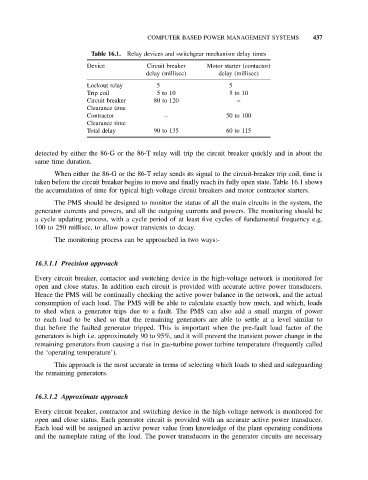
Table 16.1. Relay devices and switchgear mechanism delay times
Device Circuit breaker Motor starter (contactor)
delay (millisec) delay (millisec)
Lockout relay 5 5
Trip coil 5 to 10 5 to 10
Circuit breaker 80 to 120 –
Clearance time
Contractor – 50 to 100
Clearance time
Total delay 90 to 135 60 to 115
detected by either the 86-G or the 86-T relay will trip the circuit breaker quickly and in about the
same time duration.
When either the 86-G or the 86-T relay sends its signal to the circuit-breaker trip coil, time is
taken before the circuit breaker begins to move and finally reach its fully open state. Table 16.1 shows
the accumulation of time for typical high-voltage circuit breakers and motor contractor starters.
The PMS should be designed to monitor the status of all the main circuits in the system, the
generator currents and powers, and all the outgoing currents and powers. The monitoring should be
a cycle updating process, with a cycle period of at least five cycles of fundamental frequency e.g.
100 to 250 millisec, to allow power transients to decay.
The monitoring process can be approached in two ways:-
16.3.1.1 Precision approach
Every circuit breaker, contactor and switching device in the high-voltage network is monitored for
open and close status. In addition each circuit is provided with accurate active power transducers.
Hence the PMS will be continually checking the active power balance in the network, and the actual
consumption of each load. The PMS will be able to calculate exactly how much, and which, loads
to shed when a generator trips due to a fault. The PMS can also add a small margin of power
to each load to be shed so that the remaining generators are able to settle at a level similar to
that before the faulted generator tripped. This is important when the pre-fault load factor of the
generators is high i.e. approximately 90 to 95%, and it will prevent the transient power change in the
remaining generators from causing a rise in gas-turbine power turbine temperature (frequently called
the ‘operating temperature’).
This approach is the most accurate in terms of selecting which loads to shed and safeguarding
the remaining generators.
16.3.1.2 Approximate approach
Every circuit breaker, contractor and switching device in the high-voltage network is monitored for
open and close status. Each generator circuit is provided with an accurate active power transducer.
Each load will be assigned an active power value from knowledge of the plant operating conditions
and the nameplate rating of the load. The power transducers in the generator circuits are necessary