Page 581 - Handbook of Electrical Engineering
P. 581
574    HANDBOOK OF ELECTRICAL ENGINEERING

               q) Simplified solution

                  In the proposed system, used as the example above, it is acceptable to ignore the cable impedance
                  R cm + jX cm and the transformer impedance R c + jX c for approximate calculation purposes. This
                  is only allowable for the following reasons:-

                  • The power system distribution cables or overhead lines are well rated for their current duty
                    and are short in length.
                  • The series impedances for cables are usually small in comparison with the transient reactances
                    and load impedances, but this is not always the case with low voltage situations where for
                    example the route lengths of cables can be relatively long.
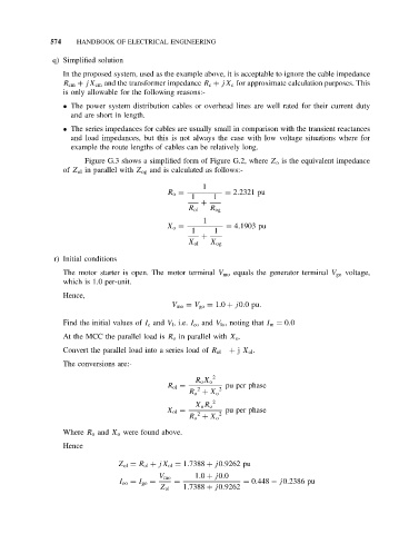
                       Figure G.3 shows a simplified form of Figure G.2, where Z o is the equivalent impedance
                  of Z ol in parallel with Z og and is calculated as follows:-

                                                      1
                                             R o =          = 2.2321 pu
                                                   1     1
                                                      +
                                                  R ol  R og
                                                      1
                                             X o =          = 4.1903 pu
                                                   1     1
                                                      +
                                                  X ol  X og
               r) Initial conditions
                  The motor starter is open. The motor terminal V mo equals the generator terminal V go voltage,
                  which is 1.0 per-unit.
                  Hence,
                                              V mo = V go = 1.0 + j0.0pu.

                  Find the initial values of I c and V l ,i.e. I co and V lo , noting that I m = 0.0
                  At the MCC the parallel load is R o in parallel with X o .

                                                             + j X ol .
                  Convert the parallel load into a series load of R ol
                  The conversions are:-
                                                         2
                                                    R o X o
                                             R ol =         pu per phase
                                                     2    2
                                                  R o + X o
                                                         2
                                                    X o R o
                                             X ol =         pu per phase
                                                     2    2
                                                  R o + X o
                  Where R o and X o were found above.
                  Hence

                                Z ol = R ol + jX ol = 1.7388 + j0.9262 pu
                                                    1.0 + j0.0
                                           V mo
                                I oo = I go =  =                 = 0.448 − j0.2386 pu
                                           Z ol  1.7388 + j0.9262

