Page 600 - Handbook of Electrical Engineering
P. 600
EARTHING CURRENT AND ELECTRIC SHOCK HAZARD POTENTIAL DIFFERENCE       593

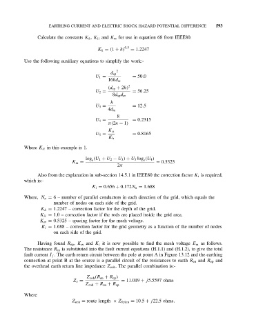
                 Calculate the constants K h , K ii and K m for use in equation 68 from IEEE80.

                                                      0.5
                                          K h = (1 + h)  = 1.2247

           Use the following auxiliary equations to simplify the work:-
                                                  2
                                                d sp
                                         U 1 =           = 50.0
                                               16hd m
                                               (d sp + 2h) 2
                                         U 2 =           = 56.25
                                                8d sp d m
                                                h
                                         U 3 =           = 12.5
                                               4d m
                                                  8
                                         U 4 =           = 0.2315
                                               π(2n − 1)
                                               K ii
                                         U 5 =           = 0.8165
                                               K h
           Where K ii in this example is 1.

                                     log (U 1 + U 2 − U 3 ) + U 5 log (U 4 )
                                        e
                                                              e
                               K m =                               = 0.5325
                                                  2π
                 Also from the explanation in sub-section 14.5.1 in IEEE80 the correction factor K i is required,
           which is:-
                                        K i = 0.656 + 0.172N n = 1.688
           Where, N n = 6 – number of parallel conductors in each direction of the grid, which equals the
                        number of nodes on each side of the grid.
                  K h = 1.2247 – correction factor for the depth of the grid.
                  K ii = 1.0 – correction factor if the rods are placed inside the grid area.
                  K m = 0.5325 – spacing factor for the mesh voltage.
                  K i = 1.688 – correction factor for the grid geometry as a function of the number of nodes
                        on each side of the grid.

                 Having found R ep , K m and K i it is now possible to find the mesh voltage E m as follows.
           The resistance R ep is substituted into the fault current equations (H.1.1) and (H.1.2), to give the total
           fault current I f . The earth return circuit between the pole at point A in Figure 13.12 and the earthing
           connection at point B at the source is a parallel circuit of the resistances to earth R en and R ep and
           the overhead earth return line impedance Z eoh . The parallel combination is:-
                                     Z eoh (R en + R ep )
                                Z e =               = 11.019 + j5.5597 ohms
                                     Z eoh + R en + R ep
           Where
                               Z eoh = route length × Z 0pkm = 10.5 + j22.5 ohms.

