
Page 597 - Handbook of Electrical Engineering
P. 597
590 HANDBOOK OF ELECTRICAL ENGINEERING
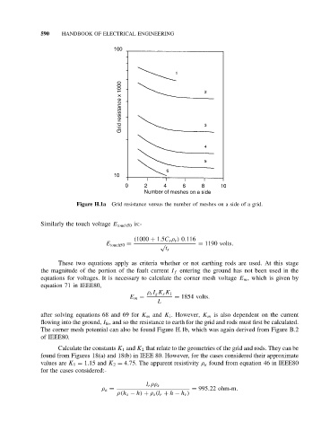
Figure H.1a Grid resistance versus the number of meshes on a side of a grid.
Similarly the touch voltage E touch50 is:-
(1000 + 1.5C s ρ s ) 0.116
E touch50 = √ = 1190 volts.
t s
These two equations apply as criteria whether or not earthing rods are used. At this stage
the magnitude of the portion of the fault current I f entering the ground has not been used in the
equations for voltages. It is necessary to calculate the corner mesh voltage E m , which is given by
equation71inIEEE80,
ρ s I g K s K i
E m = = 1854 volts.
L
after solving equations 68 and 69 for K m and K i .However, K m is also dependent on the current
flowing into the ground, I fe , and so the resistance to earth for the grid and rods must first be calculated.
The corner mesh potential can also be found Figure H.1b, which was again derived from Figure B.2
of IEEE80.
Calculate the constants K 1 and K 2 that relate to the geometries of the grid and rods. They can be
found from Figures 18(a) and 18(b) in IEEE 80. However, for the cases considered their approximate
values are K 1 = 1.15 and K 2 = 4.75. The apparent resistivity ρ a found from equation 46 in IEEE80
for the cases considered:-
l r ρρ s
ρ a = = 995.22 ohm-m.
ρ(h s − h) + ρ s (l r + h − h r )