
Page 594 - Handbook of Electrical Engineering
P. 594
EARTHING CURRENT AND ELECTRIC SHOCK HAZARD POTENTIAL DIFFERENCE 587
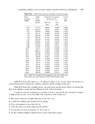
Table H.1a. Earth fault current as a function of earth resistance
Earth Earth Proportion of current X-to-R
resistance fault diverted to the ratio
(ohms) current (pu)
(amps) O/H line Pole
(pu) (pu)
0.25 1314.73 0.0683 0.9692 1.6023
0.50 1310.23 0.0777 0.9647 1.5876
0.75 1305.70 0.0870 0.9601 1.5736
1.00 1301.13 0.0962 0.9555 1.5602
1.25 1296.54 0.1053 0.9509 1.5474
1.50 1201.92 0.1143 0.9463 1.5351
1.75 1287.30 0.1233 0.9416 1.5233
2.00 1282.66 0.1321 0.9370 1.5121
4.00 1245.83 0.1992 0.8993 1.4383
6.00 1210.65 0.2603 0.8617 1.3874
8.00 1178.15 0.3156 0.8248 1.3532
10.0 1148.73 0.3654 0.7890 1.3311
15.0 1088.41 0.4695 0.7065 1.3094
20.0 1043.88 0.5496 0.6347 1.3141
25.0 1010.86 0.6120 0.5734 1.3307
30.0 985.98 0.6611 0.5211 1.3523
35.0 966.84 0.7005 0.4754 1.3754
40.0 951.83 0.7325 0.4382 1.3985
50.0 930.11 0.7808 0.3765 1.4417
60.0 915.38 0.8153 0.3292 1.4794
70.0 904.88 0.8409 0.2920 1.5120
80.0 897.07 0.8605 0.2622 1.5399
90.0 891.08 0.8760 0.2377 1.5640
100.0 886.36 0.8885 0.2173 1.5850
Note 1. These are in relation to the magnitude of the total current, since
both currents are complex quantities having different phase angles.
Table H.1a shows the value of I f for different values of R ep . It also shows the division of
current between the overhead line earthing conductor and the footings of the pole.
Table H.1b shows the ‘doubling factor’, the peak factor and the power factor of currents that
flow in an inductive circuit that has different X-to-R or R-to-X factors.
A small site may be constrained by a number of factors. Assume the site is located in a region
of high resistivity with a low water table. The constraints on the design are:-
• The surface resistivity is higher than that of the lower soil.
• A grid with earthing rods attached will be needed.
• Use a rod diameter no less than 0.01 m.
• Allow the rods to be driven deep into the ground.
2
• Use the least site area as possible, i.e. 30 to 256 m .
• Let the overhead earthing conductor divert some of the fault current.