
Page 101 - Handbook of Energy Engineering Calculations
P. 101
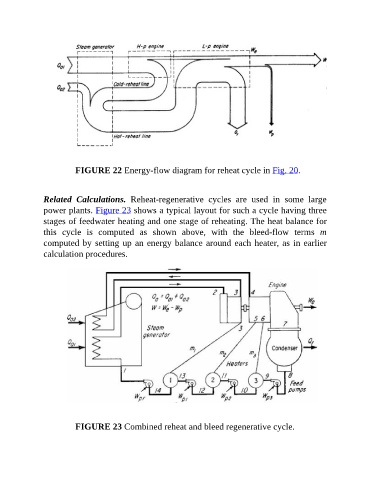
FIGURE 22 Energy-flow diagram for reheat cycle in Fig. 20.


               Related  Calculations.  Reheat-regenerative  cycles  are  used  in  some  large

               power plants. Figure 23 shows a typical layout for such a cycle having three
               stages of feedwater heating and one stage of reheating. The heat balance for
               this  cycle  is  computed  as  shown  above,  with  the  bleed-flow  terms  m
               computed by setting up an energy balance around each heater, as in earlier

               calculation procedures.


                          FIGURE 23 Combined reheat and bleed regenerative cycle.