
Page 382 - Handbook of Energy Engineering Calculations
P. 382
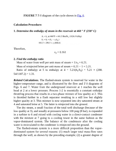
FIGURE 7 T-S diagram of the cycle shown in Fig. 6.


               Calculation Procedure:


               1. Determine the enthalpy of steam in the reservoir at 460 ° F (238° C)


               Therefore,

                                                          x  = 0.161
                                                            3

               2. Find the enthalpy ratio
                  Mass of water from well per unit mass of steam = 1/x  = 6.21.
                                                                                  3
                  Mass of reinjected brine per unit mass of steam = 6.21 − 1 = 5.21.
                  Ratio  of  enthalpy  at  5  to  enthalpy  at  4  =  5.21(h /h )  =  5.21  ×  (298.
                                                                                      4
                                                                                  5
               54/1187.2) = 1.31.


               Related Calculations. The flashed-steam system is reserved for water in the
               higher-temperature range, and is illustrated by the flow and T-S diagrams of
               Figs. 6 and 7. Water from the underground reservoir at 1 reaches the well

               head at 2 at a lower pressure. Process 1-2 is essentially a constant enthalpy
               throttling process that results in a two-phase mixture of low quality at 2. This
               is  throttled  further  in  a  flash  separator  resulting  in  a  still  low  but  slightly
               higher quality at 3. This mixture is now separated into dry saturated steam at

               4 and saturated brine at 5. The latter is reinjected into the ground.
                  The dry steam, a small fraction of the total well discharge (because of the
               low quality at 3), and usually at pressures below 100 psig (8 bar), is expanded
               in a turbine to 6 and mixed with cooling water in a direct-contact condenser

               with  the  mixture  at  7  going  to  a  cooling  tower  in  the  same  fashion as  the
               vapor-dominated  system.  The  balance  of  the  condensate  after  the  cooling
               water is recirculated to the condenser is reinjected into the ground.
                  The flashed-steam system is a more difficult proposition than the vapor-

               dominated system for several reasons: (1) much larger total mass-flow rates
               through the well, as shown by the preceding example; (2) a greater degree of