Page 406 - Handbook of Energy Engineering Calculations
P. 406

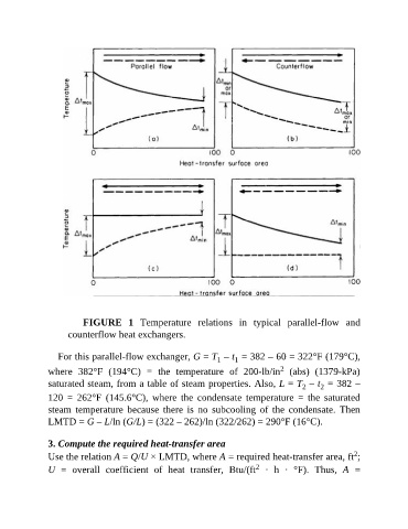
FIGURE  1  Temperature  relations  in  typical  parallel-flow  and
                     counterflow heat exchangers.

                  For this parallel-flow exchanger, G = T  – t  = 382 – 60 = 322°F (179°C),
                                                                       1
                                                                  1
                                                                                     2
               where  382°F  (194°C)  =  the  temperature  of  200-lb/in   (abs)  (1379-kPa)
               saturated steam, from a table of steam properties. Also, L = T  – t  = 382 –
                                                                                                 2
                                                                                            2
               120  =  262°F  (145.6°C),  where  the  condensate  temperature  =  the  saturated
               steam  temperature  because  there  is  no  subcooling  of  the  condensate.  Then
               LMTD = G – L/ln (G/L) = (322 – 262)/ln (322/262) = 290°F (16°C).


               3. Compute the required heat-transfer area
                                                                                                           2
               Use the relation A = Q/U × LMTD, where A = required heat-transfer area, ft ;
                                                                              2
               U  =  overall  coefficient  of  heat  transfer,  Btu/(ft   ·  h  ·  °F).  Thus,  A  =
   401   402   403   404   405   406   407   408   409   410   411