
Page 408 - Handbook of Energy Engineering Calculations
P. 408
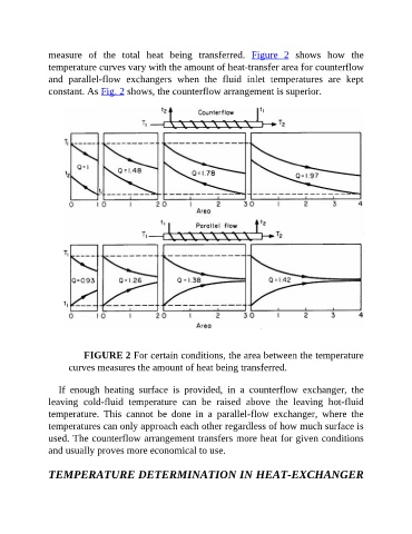
measure  of  the  total  heat  being  transferred.  Figure  2  shows  how  the
               temperature curves vary with the amount of heat-transfer area for counterflow
               and  parallel-flow  exchangers  when  the  fluid  inlet  temperatures  are  kept
               constant. As Fig. 2 shows, the counterflow arrangement is superior.


                          FIGURE 2 For certain conditions, the area between the temperature
                     curves measures the amount of heat being transferred.


                  If  enough  heating  surface  is  provided,  in  a  counterflow  exchanger,  the
               leaving  cold-fluid  temperature  can  be  raised  above  the  leaving  hot-fluid
               temperature.  This  cannot  be  done  in  a  parallel-flow  exchanger,  where  the
               temperatures can only approach each other regardless of how much surface is
               used. The counterflow arrangement transfers more heat for given conditions

               and usually proves more economical to use.


               TEMPERATURE DETERMINATION IN HEAT-EXCHANGER