
Page 413 - Handbook of Energy Engineering Calculations
P. 413
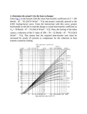
2. Determine the actual U for the heat exchanger

               Enter Fig. 5 at the bottom with the clean heat-transfer coefficient of U = 100
                                                     2
                            2
               Btu/(h · ft  · °F) [567.8 W/(m  · °C)] and project vertically upward to the
               0.002  fouling-factor  curve.  From  the  intersection  with  this  curve,  project
               horizontally to the left to read the design or actual heat-transfer coefficient as
                                                              2
                                      2
               U  = 78 Btu/(h · ft  · °F) [442.9 W/(m  · °C)]. Thus, the fouling of the tubes
                  a
                                                                                            2
               causes a reduction of the U value of 100 – 78 = 22 Btu/(h · ft  · °F) [124.9
                      2
               W/(m   ·  °C)].  This  means  that  the  required  heat-transfer  area  must  be
               increased  by  nearly  25  percent  to  compensate  for  the  reduction  in  heat

               transfer caused by fouling.