
Page 426 - Handbook of Energy Engineering Calculations
P. 426
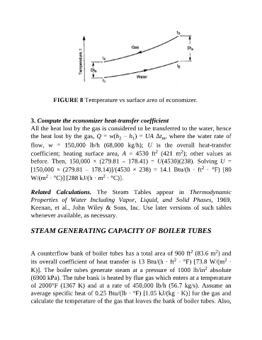
FIGURE 8 Temperature vs surface area of economizer.


               3. Compute the economizer heat-transfer coefficient

               All the heat lost by the gas is considered to be transferred to the water, hence
               the heat lost by the gas, Q = w(h  – h ) = UA Δt , where the water rate of
                                                         2
                                                               1
                                                                            m
               flow,  w  =  150,000  lb/h  (68,000  kg/h);  U  is  the  overall  heat-transfer
                                                                                     2
                                                                          2
               coefficient;  heating  surface  area,  A  =  4530  ft   (421  m );  other  values  as
               before.  Then,  150,000  ×  (279.81  –  178.41)  =  U(4530)(238).  Solving  U  =
                                                                                               2
               [150,000  ×  (279.81  –  178.14)]/(4530  ×  238)  =  14.1  Btu/(h  ·  ft   ·  °F)  [80
                      2
                                                 2
               W/(m  · °C)] [288 kJ/(h · m  · °C)].
               Related  Calculations.  The  Steam  Tables  appear  in  Thermodynamic

               Properties  of  Water  Including  Vapor,  Liquid,  and  Solid  Phases,  1969,
               Keenan,  et  al.,  John  Wiley  &  Sons,  Inc.  Use  later  versions  of  such  tables
               whenever available, as necessary.


               STEAM GENERATING CAPACITY OF BOILER TUBES


                                                                                                      2
                                                                                          2
               A counterflow bank of boiler tubes has a total area of 900 ft  (83.6 m ) and
                                                                                  2
                                                                                                          2
               its overall coefficient of heat transfer is 13 Btu/(h · ft  · °F) [73.8 W/(m  ·
                                                                                                 2
               K)].  The  boiler  tubes  generate  steam  at  a  pressure  of  1000  lb/in   absolute
               (6900 kPa). The tube bank is heated by flue gas which enters at a temperature
               of  2000°F  (1367  K)  and  at  a  rate  of  450,000  lb/h  (56.7  kg/s).  Assume  an

               average specific heat of 0.25 Btu/(lb · °F) [1.05 kJ/(kg · K)] for the gas and
               calculate the temperature of the gas that leaves the bank of boiler tubes. Also,