
Page 429 - Handbook of Energy Engineering Calculations
P. 429
below prevail. This exchanger will be of the single tube-pass and single shell-
pass design Table 5, with countercurrent flows of the tubeside and shellside
fluids.
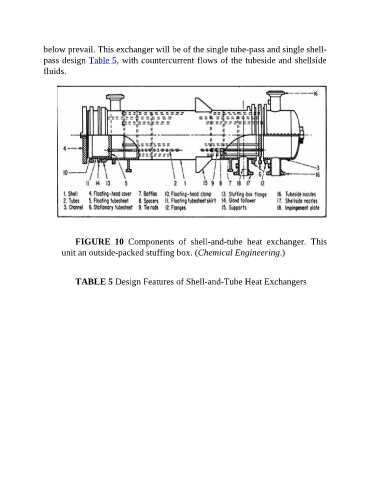
FIGURE 10 Components of shell-and-tube heat exchanger. This
unit an outside-packed stuffing box. (Chemical Engineering.)
TABLE 5 Design Features of Shell-and-Tube Heat Exchangers