Page 458 - Handbook of Energy Engineering Calculations
P. 458
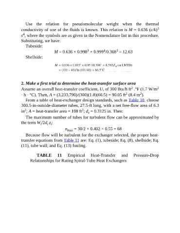
Use  the  relation  for  pseudomolecular  weight  when  the  thermal
               conductivity of one of the fluids is known. This relation is M = 0.636 (c/k)                 3
                 4
               s , where the symbols are as given in the Nomenclature list in this procedure.
               Substituting, we have:
                  Tubeside:
                                                                       4
                                                                                3
                                                            3
                                      M = 0.636 × 0.998  × 0.999 /0.368  = 12.63
                  Shellside:


               2. Make a first trial to determine the heat-transfer surface area
                                                                                          2
               Assume an overall heat-transfer coefficient, U, of 300 Btu/h ft  .°F (1.7 W/m                2
                                                                                      2
                                                                                                2
               · h · °C). Then, A = (3,233,790)/(300)(1.8)(66.5) = 90.05 ft  (8.4 m ).
                  From a table of heat-exchanger design standards, such as Table 10, choose
               300.5-in-outside-diameter tubes, 27.5-ft long, with a net free-flow area of 6.3
                                                         2
                  2
               in ; A = heat-transfer area = 108 ft ; d  = 0.3125 in. Then:
                                                             s
                  The maximum number of tubes for turbulent flow can be approximated by
               the term W /2d  z :
                             i
                                 i i
                                             n max  = 30/2 × 0.402 × 0.55 = 68

                  Because flow will be turbulent for the exchanger selected, the proper heat-
               transfer equations from Table 11 are: Eq. (1), tubeside; Eq. (8), shellside; Eq.
               (11), tube wall; and Eq. (13) fouling.


                          TABLE         11     Empirical       Heat-Transfer       and      Pressure-Drop

                     Relationships for Rating Spiral-Tube Heat Exchangers

