
Page 138 - Handbook of Materials Failure Analysis
P. 138
134 CHAPTER 6 Failure analysis of concrete sleepers/bearers
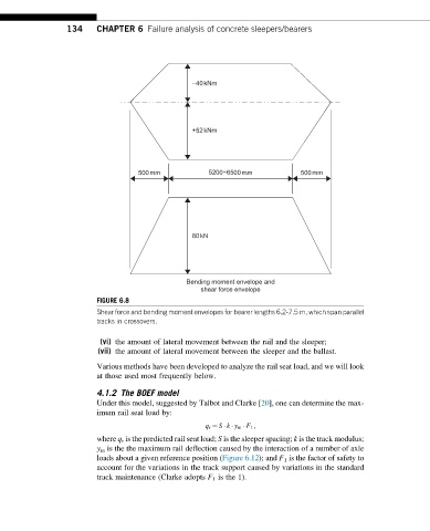
−40kNm
+52kNm
500 mm 5200−6500 mm 500mm
80kN
Bending moment envelope and
shear force envelope
FIGURE 6.8
Shear force and bending moment envelopes for bearer lengths 6.2-7.5 m, which span parallel
tracks in crossovers.
(vi) the amount of lateral movement between the rail and the sleeper;
(vii) the amount of lateral movement between the sleeper and the ballast.
Various methods have been developed to analyze the rail seat load, and we will look
at those used most frequently below.
4.1.2 The BOEF model
Under this model, suggested by Talbot and Clarke [20], one can determine the max-
imum rail seat load by:
q r ¼ S k y m F 1 ;
where q r is the predicted rail seat load; S is the sleeper spacing; k is the track modulus;
y m is the the maximum rail deflection caused by the interaction of a number of axle
loads about a given reference position (Figure 6.12); and F 1 is the factor of safety to
account for the variations in the track support caused by variations in the standard
track maintenance (Clarke adopts F 1 is the 1).