Page 143 - Handbook of Materials Failure Analysis
P. 143

4 Current Analysis and Design Methods    139


                     65


                    Wheel load carried by an individual sleeper (%)
                     60
                                                                                  D
                     55
                                                                                  B

                     50
                                                                                  C

                     45
                                                                                  A

                     40


                     35


                     30
                      500                 600                 700                800
                                             Sleeper spacing (mm)
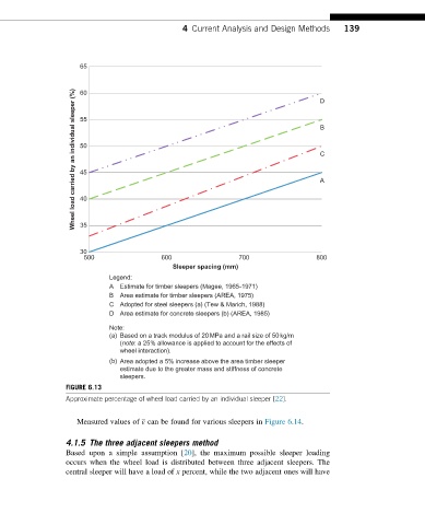
                             Legend:
                             A  Estimate for timber sleepers (Magee, 1965-1971)
                             B  Area estimate for timber sleepers (AREA, 1975)
                             C Adopted for steel sleepers (a) (Tew & Marich, 1988)
                             D Area estimate for concrete sleepers (b) (AREA, 1985)

                             Note:
                             (a) Based on a track modulus of 20MPa and a rail size of 50kg/m
                               (note: a 25% allowance is applied to account for the effects of
                               wheel interaction).
                             (b) Area adopted a 5% increase above the area timber sleeper
                               estimate due to the greater mass and stiffness of concrete
                               sleepers.
                  FIGURE 6.13
                  Approximate percentage of wheel load carried by an individual sleeper [22].

                     Measured values of ε can be found for various sleepers in Figure 6.14.


                  4.1.5 The three adjacent sleepers method
                  Based upon a simple assumption [20], the maximum possible sleeper loading
                  occurs when the wheel load is distributed between three adjacent sleepers. The
                  central sleeper will have a load of x percent, while the two adjacent ones will have
   138   139   140   141   142   143   144   145   146   147   148