
Page 144 - Handbook of Materials Failure Analysis
P. 144
140 CHAPTER 6 Failure analysis of concrete sleepers/bearers
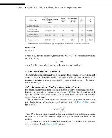
Sleep dimensions Sleeper Area of sleeper
length ¥ breadth ¥ rail seat q
Sleeper type spacing support Q ε = r
thickness 3 2 (mm) P
(mm) (mm) (10 mm ) s
French, type VW
Prestressed concrete 2300 × 250 × 140 600 200 400 0.56-0.59
British, type F
Prestressed concrete 2515 × 264 × 200 760 268.8 510 0.32-0.44
German, type 58 2400 × 280 × 190 600 252 450 0.32-0.44
Prestressed concrete
French, Hardwood 2600 × 255 × 135 600 280.5 550 0.46-0.76
The area of sleeper support = 2Q × sleeper width at rail seat, where Q = distance of the centre line of the rail from
the end of the sleeper.
FIGURE 6.14
Values of ε .
a value of x/2 percent. Therefore, the value of x will be 0.5, and hence the maximum
rail seat load is:
q r ¼ 0:5P;
where P is the design wheel load; q r is the predicted rail seat load.
4.2 SLEEPER BENDING MOMENTS
The material chosen for the analysis of maximum sleeper bending at the rail seat and
center is irrelevant, but rather the flexural limits, usually expressed in the form of
positive or negative bending moment capacity in concrete, imposed on the sleeper
varies accordingly.
4.2.1 Maximum sleeper bending moment at the rail seat
For determining the maximum bending, a uniform effective contact pressure distri-
bution between the sleeper and the ballast is assumed [20] and the calculations based
upon this simple assumption would yield an upper-bound solution sufficient for
sleeper design purposes.
In the upper-bound solution, it is assumed that the support from the ballast is a
point load at the end of the sleeper, equal to the rail seat load (Figure 6.15a), giving
the equation:
l g
M r ¼ q r ;
2
where M r is the maximum sleeper bending moment at rail seat; q r is the maximum
rail seat load; l is the overall sleeper length; and g is the distance between the rail
centers.
A more realistic method assumes half the rail seat load is distributed over the
sleeper overhand length (Figure 6.15b), giving: