
Page 149 - Handbook of Materials Failure Analysis
P. 149
4 Current Analysis and Design Methods 145
q q
g
Prestressed
concrete sleeper
I
W
I−g I−g
(a) Pressure distribution for maximum rail seat moment (positive)
W
0.9(I−g) 0.8(I−g)
Standard gauge Narrow gauge
(b) Pressure distribution for maximum centremoment (positive)`
0.5 W
W
I−g I−g
(c) Pressure distribution for maximum centre moment (negative)
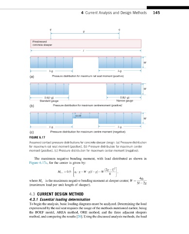
FIGURE 6.17
Assumed contact pressure distributions for concrete sleeper design. (a) Pressure distribution
for maximum rail seat moment (positive). (b) Pressure distribution for maximum center
moment (positive). (c) Pressure distribution for maximum center moment (negative).
The maximum negative bending moment, with load distributed as shown in
Figure 6.17c, for the center is given by:
" #
2
ð 2g lÞ
M c ¼ 0:5 q r g W gl gÞ W ;
ð
8
4q r
where M c is the maximum negative bending moment at sleeper center; W ¼
3l 2g
(maximum load per unit length of sleeper).
4.3 CURRENT DESIGN METHOD
4.3.1 Essential loading determination
To begin the analysis, basic loading diagrams must be analyzed. Determining the load
experienced by the rail seat requires the usage of the methods mentioned earlier, being
the BOEF model, AREA method, ORE method, and the three adjacent sleepers
method, and comparing the results [20]. Using the discussed analysis methods, the load