
Page 147 - Handbook of Materials Failure Analysis
P. 147
4 Current Analysis and Design Methods 143
where M r is the maximum positive sleeper bending moment at rail seat; l is the total
sleeper length; g is the distance between rail centers; W is the assumed uniformly
distributed load.
The maximum negative bending moment at the center is given by:
Wg 2
M c ¼ M r ;
8
where M c is the maximum negative bending moment at the center of the sleeper.
By combining these two equations, the solution is
ð 2g lÞ
M c ¼ q r :
4
This moment calculated is considered adequate under normal service conditions, but
sleeper cracking will still occur due to abnormally high loads.
4.2.3.2 The ORE design method
The ORE design method is based upon experimental data from both laboratory and
actual track conditions. It also assumes the maximum rail seat load to be that calcu-
lated with the ORE method [20].
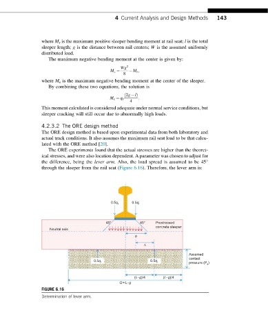
The ORE experiments found that the actual stresses are higher than the theoret-
ical stresses, and were also location dependent. A parameter was chosen to adjust for
the difference, being the lever arm. Also, the load spread is assumed to be 45°
through the sleeper from the rail seat (Figure 6.16). Therefore, the lever arm is:
r r
0.5q 0.5q
45° 45° Prestressed
concrete sleeper
Neutral axis
b
Λ
Assumed
contact
0.5q r 0.5q r )
pressure (P a
(L-g)/4 (L-g)/4
Q = L-g
FIGURE 6.16
Determination of lever arm.