
Page 150 - Handbook of Materials Failure Analysis
P. 150
146 CHAPTER 6 Failure analysis of concrete sleepers/bearers
Table 6.2 Adjusted Rail Seat Loading for Bearer Spacing 621 mm
Maximum Rail Seat Load Maximum Rail Seat Load
Method (kN, 760 mm) (kN, 621 mm)
Three adjacent q r ¼0.50P q r ¼0.50P a
method
BOEF model q r ¼0.43P q r ¼0.35P
AREA method q r ¼0.60P q r ¼0.49P
ORE method q r ¼0.65P q r ¼0.53P
a
Three adjacent method is a constant 0.50P regardless of spacing.
for a sleeper spacing of 621 mm can be approximated by adjusting for the sleeper spac-
ing, which is proportional in the earlier equations, with the results shown in Table 6.2.
Determining the contribution of the design and track layout to the failure of the
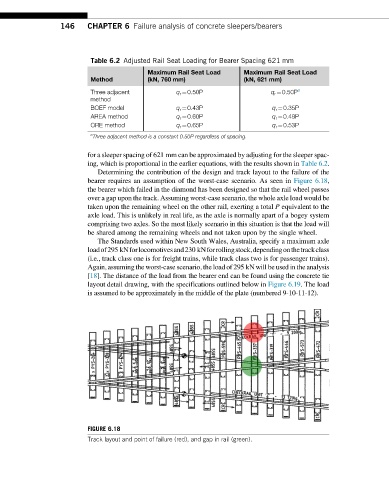
bearer requires an assumption of the worst-case scenario. As seen in Figure 6.18,
the bearer which failed in the diamond has been designed so that the rail wheel passes
over a gap upon the track. Assuming worst-case scenario, the whole axle load would be
taken upon the remaining wheel on the other rail, exerting a total P equivalent to the
axle load. This is unlikely in real life, as the axle is normally apart of a bogey system
comprising two axles. So the most likely scenario in this situation is that the load will
be shared among the remaining wheels and not taken upon by the single wheel.
The Standards used within New South Wales, Australia, specify a maximum axle
loadof295 kNforlocomotivesand230 kNforrollingstock,dependingonthetrackclass
(i.e., track class one is for freight trains, while track class two is for passenger trains).
Again, assuming the worst-case scenario, the load of 295 kN will be used in the analysis
[18]. The distance of the load from the bearer end can be found using the concrete tie
layout detail drawing, with the specifications outlined below in Figure 6.19.The load
is assumed to be approximately in the middle of the plate (numbered 9-10-11-12).
FIGURE 6.18
Track layout and point of failure (red), and gap in rail (green).