
Page 154 - Handbook of Materials Failure Analysis
P. 154
150 CHAPTER 6 Failure analysis of concrete sleepers/bearers
Table 6.3 Distance Between Bogey and Axles
Train 1 2 3 4
Axle distance 2300 2400 2440 2440
Bogey distance 3998 3876 4670 3831
Axle distance 2300 2400 2440 2440
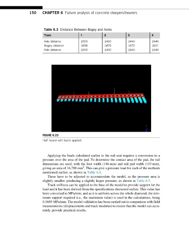
FIGURE 6.23
Half bearer with loads applied.
Applying the loads calculated earlier to the rail seat requires a conversion to a
pressure over the area of the pad. To determine the contact area of the pad, the rail
dimensions are used, with the foot width (146 mm) and rail pad width (115 mm),
2
giving an area of 16,790 mm . This can give a pressure load for each of the methods
mentioned earlier, as shown in Table 6.4.
These have to be adjusted to accommodate the model, as the pressure area is
slightly smaller, producing a slightly larger pressure, as shown in Table 6.5.
Track stiffness can be applied to the base of the model to provide support for the
load and it has been derived from the specifications discussed earlier. This value has
been converted to MPa/mm, and as it is uniform across the whole diamond, the min-
imum support required (i.e., the maximum value) is used in the calculations, being
0.1689 MPa/mm. The model validation has been carried out in comparison with field
measurements (displacements and track modulus) to ensure that the model can accu-
rately provide practical results.