
Page 157 - Handbook of Materials Failure Analysis
P. 157
6 Results and Discussions 153
Table 6.5 Actual Model Loading Pressure for Respective Rail Seat Loads
2
Method Model Rail Seat Area (mm ) Rail Seat Pressure (MPa)
Three adjacent 14,820 9.953
method
BOEF model 14,820 6.967
AREA method 14,820 9.754
ORE method 14,820 10.550
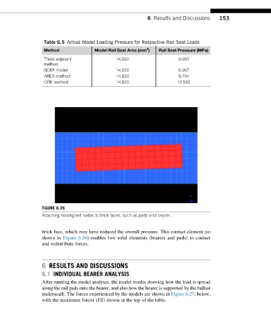
FIGURE 6.26
Attaching nonaligned nodes to brick faces, such as pads onto bearer.
brick face, which may have reduced the overall pressure. This contact element (as
shown in Figure 6.26) enables two solid elements (bearers and pads) to contact
and redistribute forces.
6 RESULTS AND DISCUSSIONS
6.1 INDIVIDUAL BEARER ANALYSIS
After running the model analyses, the model results showing how the load is spread
along the rail pads onto the bearer, and also how the bearer is supported by the ballast
underneath. The forces experienced by the models are shown in Figure 6.27, below,
with the maximum forces (FZ) shown at the top of the table.