
Page 142 - Handbook of Materials Failure Analysis
P. 142
138 CHAPTER 6 Failure analysis of concrete sleepers/bearers
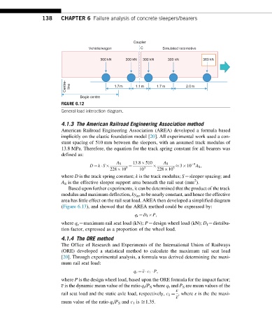
Coupler
Vehicle/wagon C Simulated locomotive
300 kN 300 kN 300 kN 300 kN 360 kN
Centre- line 1.7 m 1.1m 1.7m 2.0m
Bogie centre
FIGURE 6.12
General load interaction diagram.
4.1.3 The American Railroad Engineering Association method
American Railroad Engineering Association (AREA) developed a formula based
implicitly on the elastic foundation model [20]. All experimental work used a con-
stant spacing of 510 mm between the sleepers, with an assumed track modulus of
13.8 MPa. Therefore, the equation for the track spring constant for all bearers was
defined as:
13:8 510
A S A S 5
D ¼ k S ¼ 3 10 A S ;
228 10 3 10 3 228 10 3
where D is the track spring constant; k is the track modulus; S¼sleeper spacing; and
2
A S is the effective sleeper support area beneath the rail seat (mm ).
Based upon further experiments, it can be determined that the product of the track
modulus and maximum deflection, ky m , to be nearly constant, and hence the effective
area has little effect on the rail seat load. AREA then developed a simplified diagram
(Figure 6.13), and showed that the AREA method could be expressed by:
q r ¼ D f P;
where q r ¼maximum rail seat load (kN); P¼design wheel load (kN); D f ¼distribu-
tion factor, expressed as a proportion of the wheel load.
4.1.4 The ORE method
The Office of Research and Experiments of the International Union of Railways
(ORE) developed a statistical method to calculate the maximum rail seat load
[20]. Through experimental analysis, a formula was derived determining the maxi-
mum rail seat load:
q r ¼ ε c 1 P;
where P is the design wheel load, based upon the ORE formula for the impact factor;
ε is the dynamic mean value of the ratio q r /P S where q r and P S are mean values of the
ε
rail seat load and the static axle load, respectively, c 1 ¼ , where ε is the the maxi-
ε
mum value of the ratio q r /P S and c 1 is ffi1.35.