
Page 201 - Handbook of Materials Failure Analysis
P. 201
5 Case Study 197
M 0
K 1/2 M K
0 1/2
H e h 0 h i M i K 1
M 1
K 0
ÈCHELLE 1/100
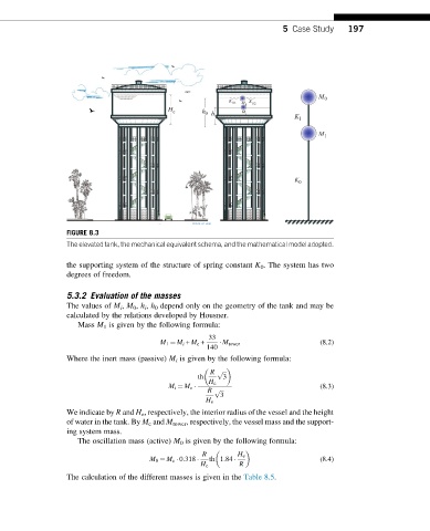
FIGURE 8.3
The elevated tank, the mechanical equivalent schema, and the mathematical model adopted.
the supporting system of the structure of spring constant K 0 . The system has two
degrees of freedom.
5.3.2 Evaluation of the masses
The values of M i , M 0 , h i , h 0 depend only on the geometry of the tank and may be
calculated by the relations developed by Housner.
Mass M 1 is given by the following formula:
33
M 1 ¼ M i + M c + M tower (8.2)
140
Where the inert mass (passive) M i is given by the following formula:
R p ffiffiffi
th 3
H e
(8.3)
M i ¼ M e
R p ffiffiffi
3
H e
We indicate by R and H e , respectively, the interior radius of the vessel and the height
of water in the tank. By M c and M tower , respectively, the vessel mass and the support-
ing system mass.
The oscillation mass (active) M 0 is given by the following formula:
R H e
(8.4)
M 0 ¼ M e 0:318 th 1:84
H e R
The calculation of the different masses is given in the Table 8.5.