
Page 250 - Handbook of Materials Failure Analysis
P. 250
246 CHAPTER 10 A reliable analysis method
2 SHOVEL STRUCTURE AND OPERATION PROCESS
2.1 STRUCTURE DESCRIPTION
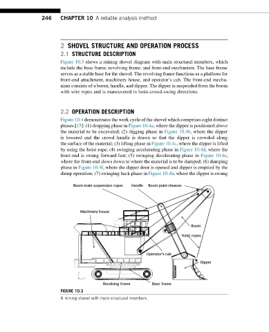
Figure 10.3 shows a mining shovel diagram with main structural members, which
include the base frame, revolving frame, and front-end mechanism. The base frame
serves as a stable base for the shovel. The revolving frame functions as a platform for
front-end attachment, machinery house, and operator’s cab. The front-end mecha-
nism consists of a boom, handle, and dipper. The dipper is suspended from the boom
with wire ropes and is maneuvered in hoist-crowd-swing directions.
2.2 OPERATION DESCRIPTION
Figure 10.4 demonstrates the work cycle of the shovel which comprises eight distinct
phases [15]: (1) dropping phase in Figure 10.4a, where the dipper is positioned above
the material to be excavated; (2) digging phase in Figure 10.4b, where the dipper
is lowered and the crowd handle is drawn so that the dipper is crowded along
the surface of the material; (3) lifting phase in Figure 10.4c, where the dipper is lifted
by using the hoist rope; (4) swinging accelerating phase in Figure 10.4d, where the
front-end is swung forward fast; (5) swinging decelerating phase in Figure 10.4e,
where the front-end slows down to where the material is to be dumped; (6) dumping
phase in Figure 10.4f, where the dipper door is opened and dipper is emptied by the
dump operation; (7) swinging back phase in Figure 10.4h, where the dipper is swung
FIGURE 10.3
A mining shovel with main structural members.