
Page 252 - Handbook of Materials Failure Analysis
P. 252
248 CHAPTER 10 A reliable analysis method
in the reverse direction; and (8) returning phase in Figure 10.4g, where the dipper is
returned to the pit and will repeat the cycle. One loading cycle generally takes
40-60 s during normal operations [3].
3 STRUCTURAL DYNAMICS ANALYSIS METHOD OF SHOVEL
FRONT-END MECHANISM
The structural dynamics model of the shovel front-end system with all the external
loadings and accelerations is created using finite element method (FEM). FEM is a
powerful technique to apply the numerical method to solve complex engineering
structural problems. In the FEM, the excavator front-end components are modeled
as the series of finite elements interconnected by nodes with the physical properties
such as elasticity modulus, Poisson’s ratio, density, yield strength, and ultimate
tensile. For the dynamic finite element stress problem, transient dynamic analysis
is proposed to determine the stress-time histories of components. And equivalent
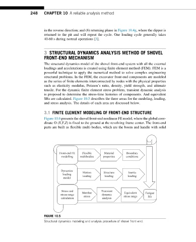
SRs are calculated. Figure 10.5 describes the three areas for the modeling, loading,
and stress analysis. The details of each area are discussed below.
3.1 FINITE ELEMENT MODELING OF FRONT-END STRUCTURE
Figure 10.6 presents the shovel front-end nonlinear FE model, where the global coor-
dinate O (X,Y,Z) is fixed to the ground at the revolving frame center. The front-end
parts are built as flexible multi-bodies, which are the boom and handle with solid
Front-end FE Flexible Material Boundary
modelling multibodies properties conditions
Dynamics
Inertia
loading Motion Structure loading
loading
loading
model
Stress and Transient
Member Equivalent Fatigue
stress range stress dynamic stress range life
calculation analysis
FIGURE 10.5
Structural dynamics modeling and analysis procedure of shovel front-end.