
Page 380 - Handbook of Materials Failure Analysis
P. 380
378 CHAPTER 14 Fatigue failure analysis of welded structures
= 0
U x
U = 0
y
= 0
U z
F x = F/2
U y = 0
U z = 0 U z = 0
y
z x
F/2
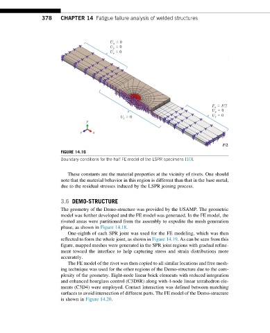
FIGURE 14.16
Boundary conditions for the half FE model of the LSPR specimens [10].
These constants are the material properties at the vicinity of rivets. One should
note that the material behavior in this region is different than that in the base metal,
due to the residual stresses induced by the LSPR joining process.
3.6 DEMO-STRUCTURE
The geometry of the Demo-structure was provided by the USAMP. The geometric
model was further developed and the FE model was generated. In the FE model, the
riveted areas were partitioned from the assembly to expedite the mesh generation
phase, as shown in Figure 14.18.
One-eighth of each SPR joint was used for the FE modeling, which was then
reflected to form the whole joint, as shown in Figure 14.19. As can be seen from this
figure, mapped meshes were generated in the SPR joint regions with gradual refine-
ment toward the interface to help capturing stress and strain distributions more
accurately.
The FE model of the rivet was then copied to all similar locations and free mesh-
ing technique was used for the other regions of the Demo-structure due to the com-
plexity of the geometry. Eight-node linear brick elements with reduced integration
and enhanced hourglass control (C3D8R) along with 4-node linear tetrahedron ele-
ments (C3D4) were employed. Contact interaction was defined between matching
surfaces to avoid intersection of different parts. The FE model of the Demo-structure
is shown in Figure 14.20.