
Page 382 - Handbook of Materials Failure Analysis
P. 382
380 CHAPTER 14 Fatigue failure analysis of welded structures
Table 14.4 Constants of the Energy-Life Equation for Different LSPR
Specimens [10]
AM30-AM60B AM60B-AZ31B AZ31B-AZ31B
P 283,184 600,424 479,112
q 2.031 2.308 1.956
(a)
(b)
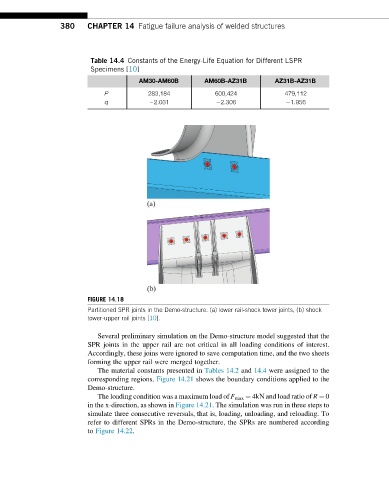
FIGURE 14.18
Partitioned SPR joints in the Demo-structure. (a) lower rail-shock tower joints, (b) shock
tower-upper rail joints [10].
Several preliminary simulation on the Demo-structure model suggested that the
SPR joints in the upper rail are not critical in all loading conditions of interest.
Accordingly, these joins were ignored to save computation time, and the two sheets
forming the upper rail were merged together.
The material constants presented in Tables 14.2 and 14.4 were assigned to the
corresponding regions. Figure 14.21 shows the boundary conditions applied to the
Demo-structure.
The loading condition was a maximum load of F max ¼ 4kN and load ratio of R ¼ 0
in the x-direction, as shown in Figure 14.21. The simulation was run in three steps to
simulate three consecutive reversals, that is, loading, unloading, and reloading. To
refer to different SPRs in the Demo-structure, the SPRs are numbered according
to Figure 14.22.