
Page 69 - Handbook of Materials Failure Analysis
P. 69
2 Case Studies 63
Failure zone
7.6 7.8 90 7.9 8.0
76
32 mm
8.3
8.3 8.2 8.2
Wall thickness (mm)
Outside diameter (mm)
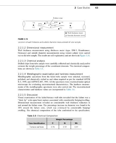
FIGURE 3.16
Locations of wall thickness and outside diameter measurement of tube sample.
2.2.1.2 Dimensional measurement
Wall thickness measurement using thickness meter (type: DM-3, Krautkramer,
Germany) and outside diameter measurements using vernier caliper were carried
out on the tube sample. The results are self-explanatory and are shown in Figure 3.16.
2.2.1.3 Chemical analysis
Drilled chips from tube sample were carefully collected and chemically analyzed to
estimate the weight percentage of the constituent elements. The chemical composi-
tions are shown in Table 3.5.
2.2.1.4 Metallographic examination and hardness measurement
Metallographic specimens from the failed tube sample were selected, sectioned,
polished, and chemically etched as and when required as per the standard ASTM
E-3, 1995, and ASTM E-407, 1993. All the specimens were examined under optical
microscope for evaluating microstructural characteristics. The hardness measure-
ments of the metallographic specimens were also carried out. The microstructural
characteristics and hardness values are incorporated in Table 3.6.
2.2.1.5 Discussion
Visual examination of the failed furnace wall tube revealed that the failure was a
“thick lip” wide-open burst rupture associated with considerable bulging/swelling.
Dimensional measurement revealed no considerable wall thickness reduction in
and around the failure zone. The percentage increase in diameter was found to be
18% around the failure zone, which was evidenced by considerable bulging/
swelling. The chemical composition of the tube conformed to the specification.
Table 3.5 Chemical Composition
Weight Percentage
Tube Identification C Si Mn
Furnace wall tube 0.15 0.12 0.47