
Page 68 - Handbook of Materials Failure Analysis
P. 68
62 CHAPTER 3 Boiler tube failures: Some case studies
2.1.1.7 Conclusion for case study 1
Based on technical information provided and the findings of laboratory study, it is
concluded that the tube had failed due to severe creep damage caused by high metal
temperature during service. The probable causes of high metal temperature may be in
sufficient flow of steam due to partial blockage, presence of thick oxide scale on ID
surface, high flue gas temperature, etc.
2.2 CASE 2: HYDROGEN DAMAGE
This investigation was conducted to determine the cause of failure of a furnace wall
tube in a 110 MW thermal power plant. Visual examination along with dimensional
measurement, chemical analysis, and hardness measurement were carried out to pre-
dict the probable cause of failure. In addition, optical microscopy was a necessary
supplement to understand the reason for the failure. It was concluded that the tube
had failed due to severe hydrogen damage.
2.2.1 Examination details
2.2.1.1 Visual inspection
The tube sample was visually inspected and following physical evidences were
noted.
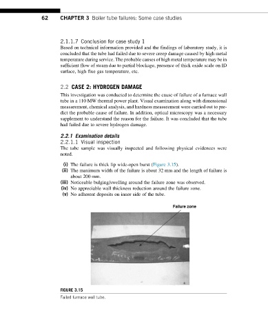
(i) The failure is thick lip wide-open burst (Figure 3.15).
(ii) The maximum width of the failure is about 32 mm and the length of failure is
about 200 mm.
(iii) Noticeable bulging/swelling around the failure zone was observed.
(iv) No appreciable wall thickness reduction around the failure zone.
(v) No adherent deposits on inner side of the tube.
FIGURE 3.15
Failed furnace wall tube.