
Page 63 - Handbook of Materials Failure Analysis
P. 63
2 Case Studies 57
B
A
D E F
Flue gas side
C
Location of failure
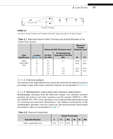
FIGURE 3.8
Locations of wall thickness and outside diameter measurement of the tube sample.
Table 3.1 Measured Values of Wall Thickness and Outside Diameter of the
Failed Tube Sample
Measured
Outside
Measured Wall Thickness (mm) Diameter (mm)
On Diametrically
Tube Location On Flue Opposite to Flue Gas
Identification (Figure 3.8) Gas Side Side XX YY
Platen A 5.2 6.1 39.62 41.1
superheater B 2.7 - 54.4 48.6
tube
C 2.3 - - -
D 3.9 5.9 40.9 40.5
E 5.5 6.3 39.5 40.0
F 5.6 5.8 - -
2.1.1.3 Chemical analysis
The material of the failed tube has been chemically analyzed and analytical results in
percentage weight of the major constituent elements are incorporated in Table 3.2.
2.1.1.4 Metallographic examination and hardness measurement
Metallographic specimens from the failed tube sample were selected, sectioned,
polished, and etched as and when required as per the standard ASTM E-3, 1995,
and ASTM E-407, 1993. All the specimens were examined under optical microscope
for evaluating microstructural characteristics. The hardness measurements of the
metallographic specimens were also carried out. The microstructural characteristics
and hardness values are incorporated in Table 3.3.
Table 3.2 Chemical Composition
Weight Percentage
Tube Identification C Cr Mo Ni Si Mn
Platen superheater tube 0.09 2.10 0.90 - - -