
Page 76 - Handbook of Materials Failure Analysis
P. 76
70 CHAPTER 4 Creep damage of high alloyed reformer tubes
This reaction proceeds at a temperature range of 850-900 °C and under pressure of
3-3.5 MPa, according to kinetics that depends on process parameters, catalyst, and
tube size [2].
Reforming tubes are very critical components being exposed to severe conditions
for long time during service. Each tube is formed by two or three pieces, produced by
centrifugal casting, machined, and butt welded. Tubes have usually inside diameter
of 60-200 mm, wall thickness in the range 10-25 mm, and total length of 10-15 m
and are designed for a nominal life of 100,000 h in service with a diameter straining
of about 3%, at temperatures and internal pressures, respectively, up to 980 °C and
35 bar [3]. The operating temperatures, together with the hoop stress due to internal
pressure, give rise to typical creep conditions: stress around 30 MPa and deformation
s .
rate of 10 10 1
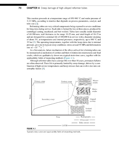
At a first analysis, failure mechanism of the alloys utilized for reforming tubes can
be summarized as nucleation of cavities and their evolution into microcracks and final
cracks, which are qualitatively shown on a typical strain-time curve, together with the
applicability fields of inspecting methods (Figure 4.1).
Although reformer tubes have a design life over than 10 years, premature failures
are often observed. Their life is primarily limited by creep damage, driven by a com-
bination of high service temperatures and hoop stresses that can evolve also into cat-
astrophic failure [4].
Macro-
Primary creep Tertiary creep
cracks
Micro-
cracks
Strain
Secondary creep Aligned
cavities
Isolated
cavities
Time Radiography
Ultrasound
Eddy current
LOTIS
FIGURE 4.1
Typical creep curve and applicability fields of inspecting methods.