
Page 77 - Handbook of Materials Failure Analysis
P. 77
1 Introduction 71
(a) (b)
FIGURE 4.2
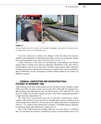
Reformer tubes put out of service: (a) diameter deformation indicated by the yellow arrow;
(b) longitudinal crack in the deformed zone.
Creep life exhaustion is evidenced by changes in the tube alloy microstructure
together with degradation of mechanical properties, giving rise to diameter elonga-
tions and longitudinal cracks after long-time service (Figure 4.2).
Cracks formation is the result of microstructure creep damage and thermal
fatigue effects resulting from uneven temperature distribution in the tube wall (in
both lengthwise and crosswise direction). Therefore, heat-resistant alloys with good
mechanical properties and corrosion resistance are required. The coast of each tube is
about 20,000 Euro, but the consequences of their sudden failure are far greater and
difficult to predict.
1.1 CHEMICAL COMPOSITION AND MICROSTRUCTURAL
FEATURES OF REFORMER TUBE
Tube materials have been widely improved over the last 50 years: formerly, in the
1960s and 1970s, the alloy mostly used was the 25Cr-20Ni-0.4C-Fe, designated as
HK-40; during the following decades, the HP-40 grade (25Cr-35Ni-0.4C-Fe) with
more Ni content has become common because of its better mechanical properties
at high operating temperature [5].
The high nickel concentrations provide an austenitic microstructure giving,
together with chromium, good mechanical strength and corrosion resistance up to
service temperatures; moreover, the increase in Ni content, especially in conjunction
with Si (>1%), improves the carburization resistance, a desirable property being the
environment inside tubes moderately carburizing [6].
Due to their high mechanical strength, tubes are not easily drawn or extruded,
thus cast structures are produced. Centrifugal casting is used to obtain a more even