
Page 82 - Handbook of Materials Failure Analysis
P. 82
76 CHAPTER 4 Creep damage of high alloyed reformer tubes
decommissioning to perform metallographic examinations and mechanical tests in
order to have a detailed description about creep damage.
It should be also underlined that an assessment of tube residual life is affected by
several uncertainty factors, such as the actual value of operating temperature (tem-
perature is measured by means of optical pyrometers with a measurement error of
20 °C); the reliable values of material creep properties (long-term properties for
such alloys are only known by manufacturer catalogues) or the actual stress state act-
ing on the tubes during service.
Moreover, in reformer tubes, thermal stresses during start-up and shut-down
stages may be significant and lead to a creep-fatigue interaction damage mechanism
[25]. As a consequence reliable means of inspection are required for a safety service
of tubes.
Currently various methods, based on different types of piping inspection
(Figure 4.1), are experimented by plant operators in order to develop a procedure
for failure forecast and prevention [26,27]. In the last decade, reforming plants have
relied on tube diameter deformation data, obtained in situ by the Laser Optic Tube
Inspection System (LOTIS) [28].
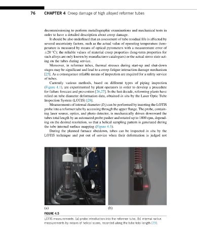
Measurements of internal diameter (D i ) can be performed by inserting the LOTIS
probe into a reformer tube by accessing through the upper flange. The probe, contain-
ing laser source, optics, and photo detector, is mechanically driven downward the
tubes total length by an automated probe pusher and rotated up to 1800 rpm, depend-
ing on the desired resolution, so that a helical sampling pattern is generated during
the tube internal surface mapping (Figure 4.5).
During the planned furnace shutdown, tubes can be inspected in situ by the
LOTIS technique and put out of service when their deformation is judged not
(a) (b)
FIGURE 4.5
LOTIS measurements: (a) probe introduction into the reformer tube, (b) internal radius
measurements by means of helical scans, recorded along the tube total length [29].